drawing 3d shapes dot paper
An engineering cartoon is a type of technical drawing that is used to convey information well-nigh an object. A common use is to specify the geometry necessary for the structure of a component and is called a detail drawing. Normally, a number of drawings are necessary to completely specify even a simple component. The drawings are linked together by a master cartoon or assembly drawing which gives the drawing numbers of the subsequent detailed components, quantities required, construction materials and mayhap 3D images that can be used to locate private items. Although mostly consisting of pictographic representations, abbreviations and symbols are used for brevity and additional textual explanations may also be provided to convey the necessary information.
The process of producing engineering drawings is often referred to equally technical cartoon or drafting (draughting).[ane] Drawings typically comprise multiple views of a component, although boosted scratch views may be added of details for farther explanation. Just the information that is a requirement is typically specified. Key information such as dimensions is usually merely specified in one place on a drawing, avoiding back-up and the possibility of inconsistency. Suitable tolerances are given for disquisitional dimensions to let the component to exist manufactured and function. More detailed production drawings may be produced based on the information given in an engineering science drawing. Drawings have an information box or championship block containing who drew the drawing, who approved it, units of dimensions, pregnant of views, the championship of the drawing and the drawing number.
History [edit]
Technical drawing has existed since ancient times. Complex technical drawings were made in renaissance times, such as the drawings of Leonardo da Vinci. Modernistic engineering drawing, with its precise conventions of orthographic projection and scale, arose in French republic at a time when the Industrial Revolution was in its infancy. L. T. C. Rolt's biography of Isambard Kingdom Brunel[2] says of his male parent, Marc Isambard Brunel, that "Information technology seems fairly certain that Marc'southward drawings of his cake-making machinery (in 1799) made a contribution to British engineering technique much greater than the machines they represented. For it is safe to assume that he had mastered the art of presenting three-dimensional objects in a two-dimensional plane which nosotros now call mechanical cartoon. It had been evolved by Gaspard Monge of Mezieres in 1765 but had remained a war machine secret until 1794 and was therefore unknown in England."[2]
Standardization and disambiguation [edit]
Engineering drawings specify requirements of a component or assembly which can exist complicated. Standards provide rules for their specification and interpretation. Standardization too aids internationalization, because people from dissimilar countries who speak different languages tin read the same engineering drawing, and interpret it the aforementioned way.
I major set up of engineering science drawing standards is ASME Y14.5 and Y14.5M (most recently revised in 2009). These apply widely in the United States, although ISO 8015 (Geometrical product specifications (GPS) — Fundamentals — Concepts, principles and rules) is now as well important.
In 2011, a new revision of ISO 8015 (Geometrical product specifications (GPS) — Fundamentals — Concepts, principles and rules) was published containing the Invocation Principle. This states that, "In one case a portion of the ISO geometric product specification (GPS) system is invoked in a mechanical engineering product documentation, the entire ISO GPS system is invoked." It also goes on to land that marking a drawing "Tolerancing ISO 8015" is optional. The implication of this is that whatsoever cartoon using ISO symbols can just exist interpreted to ISO GPS rules. The only fashion not to invoke the ISO GPS system is to invoke a national or other standard. Britain, BS 8888 (Technical Production Specification) has undergone of import updates in the 2010s.
Media [edit]
For centuries, until the 1970s, all engineering drawing was done manually by using pencil and pen on paper or other substrate (east.chiliad., vellum, mylar). Since the appearance of computer-aided design (CAD), technology drawing has been washed more and more in the electronic medium with each passing decade. Today most engineering science drawing is done with CAD, but pencil and paper have not entirely disappeared.
Some of the tools of transmission drafting include pencils, pens and their ink, straightedges, T-squares, French curves, triangles, rulers, protractors, dividers, compasses, scales, erasers, and tacks or push pins. (Slide rules used to number among the supplies, too, merely nowadays even manual drafting, when it occurs, benefits from a pocket reckoner or its onscreen equivalent.) And of course the tools also include drawing boards (drafting boards) or tables. The English idiom "to go back to the cartoon lath", which is a figurative phrase significant to rethink something altogether, was inspired past the literal act of discovering design errors during production and returning to a drawing board to revise the applied science drawing. Drafting machines are devices that assist transmission drafting past combining drawing boards, straightedges, pantographs, and other tools into one integrated drawing environment. CAD provides their virtual equivalents.
Producing drawings ordinarily involves creating an original that is then reproduced, generating multiple copies to exist distributed to the shop floor, vendors, visitor archives, and so on. The classic reproduction methods involved blue and white appearances (whether white-on-blue or blue-on-white), which is why technology drawings were long called, and fifty-fifty today are still often called, "blueprints" or "bluelines", even though those terms are anachronistic from a literal perspective, since most copies of applied science drawings today are made by more than modern methods (often inkjet or laser printing) that yield black or multicolour lines on white paper. The more generic term "impress" is now in common usage in the U.Southward. to hateful any paper copy of an engineering science drawing. In the example of CAD drawings, the original is the CAD file, and the printouts of that file are the "prints".
Systems of dimensioning and tolerancing [edit]
Nearly all applied science drawings (except mayhap reference-only views or initial sketches) communicate non only geometry (shape and location) but also dimensions and tolerances[one] for those characteristics. Several systems of dimensioning and tolerancing have evolved. The simplest dimensioning organization simply specifies distances between points (such as an object'due south length or width, or hole center locations). Since the advent of well-adult interchangeable manufacture, these distances have been accompanied by tolerances of the plus-or-minus or min-and-max-limit types. Coordinate dimensioning involves defining all points, lines, planes, and profiles in terms of Cartesian coordinates, with a common origin. Coordinate dimensioning was the sole best option until the post-Earth War Ii era saw the development of geometric dimensioning and tolerancing (GD&T), which departs from the limitations of coordinate dimensioning (eastward.thou., rectangular-just tolerance zones, tolerance stacking) to permit the nearly logical tolerancing of both geometry and dimensions (that is, both form [shapes/locations] and sizes).
Mutual features [edit]
Drawings convey the following critical information:
- Geometry – the shape of the object; represented as views; how the object will expect when it is viewed from diverse angles, such as front, top, side, etc.
- Dimensions – the size of the object is captured in accepted units.
- Tolerances – the commanded variations for each dimension.
- Material – represents what the item is made of.
- Cease – specifies the surface quality of the item, functional or corrective. For example, a mass-marketed product usually requires a much college surface quality than, say, a component that goes inside industrial machinery.
Line styles and types [edit]

Standard technology drawing line types
A variety of line styles graphically represent physical objects. Types of lines include the post-obit:
- visible – are continuous lines used to depict edges direct visible from a particular angle.
- hidden – are short-dashed lines that may be used to represent edges that are not directly visible.
- eye – are alternately long- and short-dashed lines that may be used to represent the axes of circular features.
- cut plane – are thin, medium-dashed lines, or thick alternately long- and double brusk-dashed that may be used to define sections for section views.
- section – are thin lines in a pattern (pattern determined past the textile being "cut" or "sectioned") used to point surfaces in section views resulting from "cutting". Section lines are usually referred to as "cantankerous-hatching".
- phantom – (not shown) are alternately long- and double brusk-dashed sparse lines used to correspond a feature or component that is not function of the specified office or assembly. Eastward.g. billet ends that may be used for testing, or the machined product that is the focus of a tooling drawing.
Lines tin also be classified by a letter nomenclature in which each line is given a letter.
- Blazon A lines show the outline of the characteristic of an object. They are the thickest lines on a drawing and done with a pencil softer than HB.
- Blazon B lines are dimension lines and are used for dimensioning, projecting, extending, or leaders. A harder pencil should exist used, such as a 2H pencil.
- Type C lines are used for breaks when the whole object is not shown. These are freehand fatigued and only for short breaks. 2H pencil
- Type D lines are like to Type C, except these are zigzagged and only for longer breaks. 2H pencil
- Type E lines indicate subconscious outlines of internal features of an object. These are dotted lines. 2H pencil
- Blazon F lines are Type Due east lines, except these are used for drawings in electrotechnology. 2H pencil
- Blazon K lines are used for centre lines. These are dotted lines, but a long line of 10–20 mm, and then a one mm gap, and then a pocket-sized line of 2 mm. 2H pencil
- Type H lines are the same as type G, except that every second long line is thicker. These bespeak the cutting plane of an object. 2H pencil
- Type One thousand lines indicate the alternate positions of an object and the line taken by that object. These are drawn with a long line of ten–20 mm, then a small-scale gap, and then a modest line of ii mm, then a gap, so another minor line. 2H pencil.
Multiple views and projections [edit]
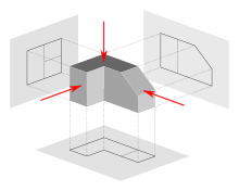
Image of a function represented in first-angle project

Symbols used to ascertain whether a projection is either first-angle (left) or 3rd-bending (right).

Several types of graphical projection compared
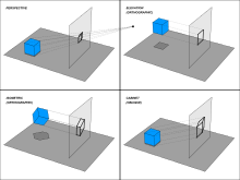
Various projections and how they are produced
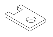
Isometric view of the object shown in the engineering cartoon below.
In most cases, a single view is not sufficient to testify all necessary features, and several views are used. Types of views include the following:
Multiview projection [edit]
A multiview projection is a type of orthographic project that shows the object as it looks from the front, right, left, top, bottom, or back (eastward.thou. the chief views), and is typically positioned relative to each other according to the rules of either first-angle or third-bending projection. The origin and vector direction of the projectors (also called projection lines) differs, as explained below.
- In beginning-bending projection, the parallel projectors originate as if radiated from behind the viewer and laissez passer through the 3D object to project a 2d paradigm onto the orthogonal plane behind it. The 3D object is projected into 2D "paper" space every bit if yous were looking at a radiograph of the object: the height view is under the front view, the right view is at the left of the front view. First-angle projection is the ISO standard and is primarily used in Europe.
- In 3rd-bending projection, the parallel projectors originate as if radiated from the far side of the object and pass through the 3D object to project a 2D paradigm onto the orthogonal aeroplane in front of information technology. The views of the 3D object are similar the panels of a box that envelopes the object, and the panels pivot as they open up flat into the plane of the drawing.[iii] Thus the left view is placed on the left and the tiptop view on the top; and the features closest to the forepart of the 3D object volition announced closest to the front end view in the drawing. Third-angle projection is primarily used in the United States and Canada, where information technology is the default projection system according to ASME standard ASME Y14.3M.
Until the belatedly 19th century, first-angle projection was the norm in North America as well as Europe;[4] [5] just circa the 1890s, 3rd-bending projection spread throughout the Due north American engineering and manufacturing communities to the indicate of becoming a widely followed convention,[four] [five] and information technology was an ASA standard past the 1950s.[five] Circa World War I, British practise was frequently mixing the apply of both project methods.[four]
As shown above, the determination of what surface constitutes the forepart, dorsum, top, and bottom varies depending on the projection method used.
Not all views are necessarily used.[six] More often than not simply as many views are used as are necessary to convey all needed information conspicuously and economically.[seven] The front, elevation, and right-side views are usually considered the core group of views included by default,[eight] only any combination of views may exist used depending on the needs of the detail blueprint. In addition to the 6 principal views (front, back, peak, bottom, right side, left side), whatsoever auxiliary views or sections may exist included equally serve the purposes of part definition and its communication. View lines or section lines (lines with arrows marked "A-A", "B-B", etc.) define the direction and location of viewing or sectioning. Sometimes a note tells the reader in which zone(southward) of the cartoon to discover the view or section.
Auxiliary views [edit]
An auxiliary view is an orthographic view that is projected into whatever airplane other than one of the six main views.[ix] These views are typically used when an object contains some sort of inclined airplane. Using the auxiliary view allows for that inclined airplane (and any other significant features) to exist projected in their true size and shape. The true size and shape of any feature in an applied science cartoon tin only be known when the Line of Sight (LOS) is perpendicular to the plane existence referenced. It is shown like a three-dimensional object. Auxiliary views tend to make use of axonometric projection. When existing all past themselves, auxiliary views are sometimes known as pictorials.
Isometric project [edit]
An isometric projection shows the object from angles in which the scales forth each centrality of the object are equal. Isometric projection corresponds to rotation of the object by ± 45° virtually the vertical axis, followed by rotation of approximately ± 35.264° [= arcsin(tan(30°))] near the horizontal axis starting from an orthographic projection view. "Isometric" comes from the Greek for "aforementioned measure". One of the things that makes isometric drawings then attractive is the ease with which 60° angles can be constructed with merely a compass and straightedge.
Isometric projection is a type of axonometric projection. The other two types of axonometric projection are:
- Dimetric project
- Trimetric project
Oblique projection [edit]
An oblique projection is a simple type of graphical projection used for producing pictorial, two-dimensional images of three-dimensional objects:
- it projects an prototype by intersecting parallel rays (projectors)
- from the iii-dimensional source object with the drawing surface (projection plan).
In both oblique projection and orthographic projection, parallel lines of the source object produce parallel lines in the projected epitome.
Perspective projection [edit]
Perspective is an approximate representation on a flat surface, of an image as it is perceived by the eye. The two most characteristic features of perspective are that objects are drawn:
- Smaller as their distance from the observer increases
- Foreshortened: the size of an object's dimensions along the line of sight are relatively shorter than dimensions across the line of sight.
Section Views [edit]
Projected views (either Auxiliary or Multiview) which testify a cantankerous section of the source object along the specified cutting plane. These views are unremarkably used to testify internal features with more clarity than may be bachelor using regular projections or hidden lines. In assembly drawings, hardware components (due east.g. basics, screws, washers) are typically not sectioned. Section view is a half side view of object.
Scale [edit]
Plans are usually "scale drawings", significant that the plans are drawn at specific ratio relative to the bodily size of the place or object. Various scales may be used for different drawings in a set. For instance, a floor program may be drawn at 1:50 (1:48 or one⁄4 ″ = 1′ 0″) whereas a detailed view may be drawn at 1:25 (1:24 or i⁄two ″ = 1′ 0″). Site plans are oft fatigued at one:200 or 1:100.
Scale is a nuanced bailiwick in the employ of engineering drawings. On i manus, it is a general principle of technology drawings that they are projected using standardized, mathematically sure projection methods and rules. Thus, keen effort is put into having an engineering science drawing accurately describe size, shape, form, aspect ratios between features, and and then on. And all the same, on the other hand, there is some other full general principle of engineering drawing that nearly diametrically opposes all this effort and intent—that is, the principle that users are not to scale the drawing to infer a dimension not labeled. This stern admonition is often repeated on drawings, via a average note in the championship cake telling the user, "Exercise NOT SCALE Drawing."
The explanation for why these two nearly opposite principles tin can coexist is as follows. The first principle—that drawings will be made so carefully and accurately—serves the prime number goal of why applied science drawing even exists, which is successfully communicating part definition and acceptance criteria—including "what the part should await like if you've made information technology correctly." The service of this goal is what creates a drawing that one even could scale and get an authentic dimension thereby. And thus the great temptation to do and so, when a dimension is wanted but was non labeled. The 2nd principle—that even though scaling the drawing will commonly work, one should nevertheless never do it—serves several goals, such as enforcing total clarity regarding who has potency to discern design intent, and preventing erroneous scaling of a drawing that was never fatigued to scale to begin with (which is typically labeled "drawing not to scale" or "scale: NTS"). When a user is forbidden from scaling the cartoon, s/he must turn instead to the engineer (for the answers that the scaling would seek), and southward/he will never erroneously scale something that is inherently unable to be accurately scaled.
But in some ways, the advent of the CAD and MBD era challenges these assumptions that were formed many decades ago. When part definition is divers mathematically via a solid model, the assertion that one cannot interrogate the model—the direct analog of "scaling the drawing"—becomes ridiculous; because when part definition is defined this fashion, it is not possible for a cartoon or model to exist "not to scale". A 2D pencil cartoon can be inaccurately foreshortened and skewed (and thus not to scale), nonetheless still be a completely valid office definition equally long as the labeled dimensions are the but dimensions used, and no scaling of the drawing past the user occurs. This is considering what the drawing and labels convey is in reality a symbol of what is wanted, rather than a true replica of it. (For example, a sketch of a hole that is conspicuously non round nonetheless accurately defines the part as having a true circular hole, every bit long as the characterization says "10mm DIA", because the "DIA" implicitly only objectively tells the user that the skewed fatigued circle is a symbol representing a perfect circle.) But if a mathematical model—essentially, a vector graphic—is declared to be the official definition of the part, then whatever amount of "scaling the drawing" can make sense; there may still be an error in the model, in the sense that what was intended is not depicted (modeled); but there can be no error of the "non to scale" type—considering the mathematical vectors and curves are replicas, not symbols, of the office features.
Even in dealing with 2D drawings, the manufacturing world has changed since the days when people paid attention to the scale ratio claimed on the impress, or counted on its accuracy. In the past, prints were plotted on a plotter to verbal scale ratios, and the user could know that a line on the cartoon 15mm long corresponded to a 30mm office dimension considering the drawing said "one:2" in the "scale" box of the championship block. Today, in the era of ubiquitous desktop press, where original drawings or scaled prints are ofttimes scanned on a scanner and saved as a PDF file, which is and then printed at whatever percent magnification that the user deems handy (such as "fit to paper size"), users have pretty much given up caring what scale ratio is claimed in the "scale" box of the title cake. Which, nether the dominion of "do not scale cartoon", never really did that much for them anyway.
Showing dimensions [edit]
Sizes of drawings [edit]


Sizes of drawings typically comply with either of ii different standards, ISO (World Standard) or ANSI/ASME Y14.one (American).
The metric cartoon sizes represent to international newspaper sizes. These developed farther refinements in the second one-half of the twentieth century, when photocopying became cheap. Engineering drawings could be readily doubled (or halved) in size and put on the next larger (or, respectively, smaller) size of paper with no waste product of infinite. And the metric technical pens were called in sizes so that i could add detail or drafting changes with a pen width irresolute by approximately a factor of the square root of 2. A full set of pens would have the following bill sizes: 0.13, 0.18, 0.25, 0.35, 0.5, 0.7, 1.0, i.5, and 2.0 mm. All the same, the International Arrangement for Standardization (ISO) called for four pen widths and set a colour code for each: 0.25 (white), 0.35 (yellow), 0.5 (brown), 0.7 (blue); these nibs produced lines that related to various text character heights and the ISO paper sizes.
All ISO newspaper sizes have the aforementioned aspect ratio, ane to the square root of two, meaning that a document designed for any given size can be enlarged or reduced to any other size and volition fit perfectly. Given this ease of irresolute sizes, it is of course mutual to copy or print a given document on different sizes of paper, especially within a series, e.g. a drawing on A3 may exist enlarged to A2 or reduced to A4.
The U.S. customary "A-size" corresponds to "letter" size, and "B-size" corresponds to "ledger" or "tabloid" size. There were also in one case British paper sizes, which went past names rather than alphanumeric designations.
American Gild of Mechanical Engineers (ASME) ANSI/ASME Y14.1, Y14.2, Y14.iii, and Y14.5 are commonly referenced standards in the U.S.
Technical lettering [edit]
Technical lettering is the procedure of forming letters, numerals, and other characters in technical cartoon. It is used to describe, or provide detailed specifications for an object. With the goals of legibility and uniformity, styles are standardized and lettering ability has niggling relationship to normal writing ability. Engineering science drawings use a Gothic sans-serif script, formed by a series of curt strokes. Lower example messages are rare in about drawings of machines. ISO Lettering templates, designed for use with technical pens and pencils, and to arrange ISO newspaper sizes, produce lettering characters to an international standard. The stroke thickness is related to the grapheme height (for example, 2.5mm high characters would have a stroke thickness - pen bill size - of 0.25mm, 3.5 would use a 0.35mm pen and so along). The ISO graphic symbol set (font) has a seriffed i, a barred seven, an open four, 6, and nine, and a circular topped three, that improves legibility when, for example, an A0 drawing has been reduced to A1 or even A3 (and perhaps enlarged dorsum or reproduced/faxed/ microfilmed &c). When CAD drawings became more popular, especially using US American software, such as AutoCAD, the nearest font to this ISO standard font was Romantic Simplex (RomanS) - a proprietary shx font) with a manually adjusted width factor (over ride) to go far look as near to the ISO lettering for the cartoon board. However, with the airtight 4, and arrondi six and nine, romans.shx typeface could be difficult to read in reductions. In more recent revisions of software packages, the TrueType font ISOCPEUR reliably reproduces the original cartoon board lettering stencil mode, however, many drawings have switched to the ubiquitous Arial.ttf.
Conventional parts (areas) [edit]
Championship cake [edit]
Every engineering drawing must take a title block.[x] [11] [12]
The title block (T/B, TB) is an area of the drawing that conveys header-type data about the drawing, such every bit:
- Drawing title (hence the name "title block")
- Cartoon number
- Office number(south)
- Name of the blueprint activity (corporation, government agency, etc.)
- Identifying code of the design action (such as a CAGE code)
- Address of the blueprint activity (such as city, state/province, state)
- Measurement units of the cartoon (for case, inches, millimeters)
- Default tolerances for dimension callouts where no tolerance is specified
- Boilerplate callouts of general specs
- Intellectual belongings rights alarm
ISO 7200 specifies the data fields used in title blocks. It standardizes eight mandatory data fields:[13]
- Title (hence the name "title cake")
- Created by (name of draughtsman)
- Approved by
- Legal owner (name of company or organization)
- Document type
- Cartoon number (same for every canvas of this document, unique for each technical certificate of the organisation)
- Sheet number and number of sheets (for example, "Sheet 5/7")
- Engagement of upshot (when the cartoon was made)
Traditional locations for the title block are the bottom right (most commonly) or the height right or centre.
Revisions block [edit]
The revisions cake (rev block) is a tabulated list of the revisions (versions) of the drawing, documenting the revision control.
Traditional locations for the revisions cake are the top right (nigh commonly) or adjoining the championship block in some way.
Next assembly [edit]
The side by side associates cake, often also referred to every bit "where used" or sometimes "effectivity block", is a list of higher assemblies where the product on the current drawing is used. This block is ordinarily found side by side to the title block.
Notes list [edit]
The notes list provides notes to the user of the cartoon, carrying whatsoever information that the callouts inside the field of the drawing did not. It may include full general notes, flagnotes, or a mixture of both.
Traditional locations for the notes list are anywhere along the edges of the field of the drawing.
General notes [edit]
General notes (G/North, GN) use more often than not to the contents of the drawing, every bit opposed to applying only to certain part numbers or certain surfaces or features.
Flagnotes [edit]
Flagnotes or flag notes (FL, F/N) are notes that apply only where a flagged callout points, such as to detail surfaces, features, or function numbers. Typically the callout includes a flag icon. Some companies call such notes "delta notes", and the note number is enclosed inside a triangular symbol (similar to uppercase letter delta, Δ). "FL5" (flagnote v) and "D5" (delta annotation five) are typical ways to abbreviate in ASCII-only contexts.
Field of the drawing [edit]
The field of the drawing (F/D, FD) is the main body or main area of the drawing, excluding the title block, rev cake, P/L and so on
List of materials, bill of materials, parts list [edit]
The list of materials (L/M, LM, LoM), bill of materials (B/M, BM, BoM), or parts list (P/L, PL) is a (ordinarily tabular) list of the materials used to make a part, and/or the parts used to make an assembly. It may comprise instructions for estrus treatment, finishing, and other processes, for each part number. Sometimes such LoMs or PLs are divide documents from the drawing itself.
Traditional locations for the LoM/BoM are higher up the title block, or in a divide document.
Parameter tabulations [edit]
Some drawings call out dimensions with parameter names (that is, variables, such a "A", "B", "C"), then tabulate rows of parameter values for each function number.
Traditional locations for parameter tables, when such tables are used, are floating nearly the edges of the field of the drawing, either virtually the title block or elsewhere forth the edges of the field.
Views and sections [edit]
Each view or section is a separate prepare of projections, occupying a contiguous portion of the field of the cartoon. Usually views and sections are chosen out with cantankerous-references to specific zones of the field.
Zones [edit]
Oftentimes a drawing is divided into zones past an alphanumeric grid, with zone labels along the margins, such as A, B, C, D up the sides and 1,2,iii,iv,5,vi forth the top and bottom.[14] Names of zones are thus, for instance, A5, D2, or B1. This characteristic greatly eases discussion of, and reference to, particular areas of the drawing.
Abbreviations and symbols [edit]
As in many technical fields, a wide array of abbreviations and symbols have been developed in engineering cartoon during the 20th and 21st centuries. For example, cold rolled steel is often abbreviated every bit CRS, and diameter is frequently abbreviated as DIA, D, or ⌀.
Virtually applied science drawings are language-independent—words are bars to the title block; symbols are used in identify of words elsewhere.[15]
With the advent of computer generated drawings for manufacturing and machining, many symbols have fallen out of mutual use. This poses a problem when attempting to translate an older hand-fatigued document that contains obscure elements that cannot be readily referenced in standard teaching text or control documents such as ASME and ANSI standards. For example, ASME Y14.5M 1994 excludes a few elements that convey critical information as independent in older US Navy drawings and aircraft manufacturing drawings of World War ii vintage. Researching the intent and meaning of some symbols can bear witness hard.
Example [edit]
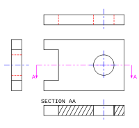
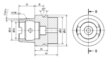
Example mechanical drawing
Here is an example of an engineering drawing (an isometric view of the aforementioned object is shown above). The unlike line types are colored for clarity.
- Blackness = object line and hatching
- Red = subconscious line
- Blueish = center line of slice or opening
- Magenta = phantom line or cutting plane line
Exclusive views are indicated past the direction of arrows, as in the instance right side.
Legal instruments [edit]
An engineering drawing is a legal document (that is, a legal instrument), considering it communicates all the needed information well-nigh "what is wanted" to the people who volition expend resources turning the idea into a reality. It is thus a office of a contract; the purchase order and the drawing together, as well every bit any coincident documents (applied science change orders [ECOs], called-out specs), constitute the contract. Thus, if the resulting product is incorrect, the worker or manufacturer are protected from liability as long every bit they accept faithfully executed the instructions conveyed by the drawing. If those instructions were wrong, it is the fault of the engineer. Because manufacturing and construction are typically very expensive processes (involving big amounts of majuscule and payroll), the question of liability for errors has legal implications.
Relationship to model-based definition (MBD/DPD) [edit]
For centuries, engineering cartoon was the sole method of transferring data from blueprint into manufacture. In recent decades another method has arisen, chosen model-based definition (MBD) or digital product definition (DPD). In MBD, the information captured past the CAD software app is fed automatically into a CAM app (computer-aided manufacturing), which (with or without postprocessing apps) creates code in other languages such equally Thousand-lawmaking to be executed by a CNC machine tool (figurer numerical control), 3D printer, or (increasingly) a hybrid machine tool that uses both. Thus today it is ofttimes the case that the data travels from the mind of the designer into the manufactured component without having ever been codified by an engineering drawing. In MBD, the dataset, not a drawing, is the legal instrument. The term "technical data package" (TDP) is now used to refer to the complete package of information (in one medium or some other) that communicates information from design to production (such as 3D-model datasets, engineering drawings, engineering modify orders (ECOs), spec revisions and addenda, and so on).
Information technology however takes CAD/CAM programmers, CNC setup workers, and CNC operators to do manufacturing, as well as other people such equally quality assurance staff (inspectors) and logistics staff (for materials handling, aircraft-and-receiving, and forepart office functions). These workers often use drawings in the course of their piece of work that have been produced from the MBD dataset. When proper procedures are being followed, a clear chain of precedence is always documented, such that when a person looks at a drawing, southward/he is told by a note thereon that this cartoon is not the governing instrument (because the MBD dataset is). In these cases, the cartoon is nevertheless a useful certificate, although legally information technology is classified as "for reference only", pregnant that if whatsoever controversies or discrepancies arise, it is the MBD dataset, not the drawing, that governs.
Encounter also [edit]
- Architectural drawing
- B. Hick and Sons – Notable drove of early locomotive and steam engine drawings
- CAD standards
- Descriptive geometry
- Certificate direction system
- Engineering science drawing symbols
- Geometric tolerance
- ISO 128 Technical drawings – Full general principles of presentation
- lite plot
- Linear scale
- Patent drawing
- Scale rulers: architect'due south scale and engineer's scale
- Specification (technical standard)
- Structural drawing
References [edit]
- ^ a b M. Maitra, Gitin (2000). Practical Engineering Drawing. 4835/24, Ansari Road, Daryaganj, New Delhi - 110002: New Historic period International (P) Express, Publishers. pp. 2–five, 183. ISBN81-224-1176-two.
{{cite book}}: CS1 maint: location (link) - ^ a b Rolt 1957, pp. 29–xxx.
- ^ French & Vierck 1953, pp. 99–105
- ^ a b c French 1918, p. 78.
- ^ a b c French & Vierck 1953, pp. 111–114
- ^ French & Vierck 1953, pp. 97–114
- ^ French & Vierck 1953, pp. 108–111
- ^ French & Vierck 1953, p. 102.
- ^ Bertoline, Gary R. Introduction to Graphics Communications for Engineers (quaternary Ed.). New York, NY. 2009
- ^ United states of america Agency of Naval Personnel. "Engineering Aid 1 & C.". 1969. p. 188.
- ^ Andres Grand. Embuido. "Engineering Assist 1 & C". 1988. p. 7-ten.
- ^ "Farm Planners' Engineering Handbook for the Upper Mississippi Region". 1953. p. 2-5.
- ^ Farhad Ghorani. "Title Block". 2015.
- ^ Paul Munford. "Technical drawing standards: Grid reference frame".
- ^ Brian Griffiths. "Applied science Drawing for Manufacture". 2002. p. 1 and p. 13.
Bibliography [edit]
- French, Thomas Due east. (1918), A manual of engineering drawing for students and draftsmen (2nd ed.), New York, New York, United states of america: McGraw-Loma, LCCN 30018430. : Engineering Drawing (volume)
- French, Thomas E.; Vierck, Charles J. (1953), A manual of engineering cartoon for students and draftsmen (eighth ed.), New York, New York, U.s.: McGraw-Loma, LCCN 52013455. : Engineering Drawing (book)
- Rolt, L.T.C. (1957), Isambard Kingdom Brunel: A Biography, Longmans Green, LCCN 57003475.
Further reading [edit]
- Basant Agrawal and C M Agrawal (2013). Engineering Drawing. Second Edition, McGraw Hill Educational activity India Pvt. Ltd., New Delhi. [1]
- Paige Davis, Karen Renee Juneau (2000). Engineering Drawing
- David A. Madsen, Karen Schertz, (2001) Applied science Drawing & Pattern. Delmar Thomson Learning. [two]
- Cecil Howard Jensen, Jay D. Helsel, Donald D. Voisinet Computer-aided engineering drawing using AutoCAD.
- Warren Jacob Luzadder (1959). Fundamentals of engineering drawing for technical students and professional.
- 1000.A. Parker, F. Pickup (1990) Technology Drawing with Worked Examples.
- Colin H. Simmons, Dennis E. Maguire Manual of engineering drawing. Elsevier.
- Cecil Howard Jensen (2001). Interpreting Engineering Drawings.
- B. Leighton Wellman (1948). Technical Descriptive Geometry. McGraw-Colina Book Company, Inc.
External links [edit]
- Examples of cubes drawn in different projections
- Blithe presentation of cartoon systems used in technical drawing (Flash animation) Archived 2011-07-06 at the Wayback Machine
- Design Handbook: Engineering Drawing and Sketching, by MIT OpenCourseWare
Source: https://en.wikipedia.org/wiki/Engineering_drawing
0 Response to "drawing 3d shapes dot paper"
Post a Comment